#statusMessage#
Do you want to start the comparison now?


Without reliable communication, safe operation is impossible. In the aerospace industry, failures are not an option. At ...

In safety-critical development and manufacturing processes, the test architecture determines quality, cost efficiency, a...

Increasing efficiency requirements in vehicles, data centers, and industry are driving new vehicle electrical system and...
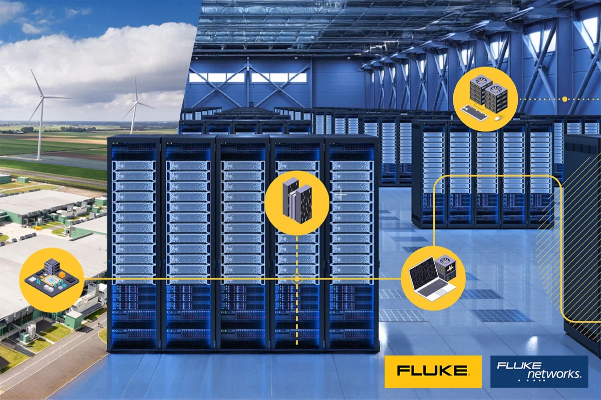
Early prevention, comprehensive certification, targeted troubleshooting. In every area of your data center, measuring in...
Network analysis at the highest level – with modern network analyzers you achieve precise and meaningful results in the characterization of high-frequency components and systems. Our experts support you in the selection, operation, and optimal utilization of these versatile measuring instruments. Discover why network analysis is indispensable in high-frequency technology, which typical challenges arise, and how you can successfully overcome them.
Some questions can be answered easily and directly on the phone. Just call us. Our experts will be happy to assist you.
.webp "Seminar LabVIEW Core 1")