#statusMessage#
Do you want to start the comparison now?


Without reliable communication, safe operation is impossible. In the aerospace industry, failures are not an option. At ...

In safety-critical development and manufacturing processes, the test architecture determines quality, cost efficiency, a...

Increasing efficiency requirements in vehicles, data centers, and industry are driving new vehicle electrical system and...
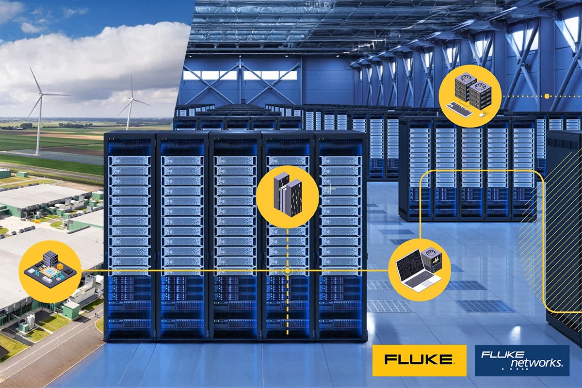
Early prevention, comprehensive certification, targeted troubleshooting. In every area of your data center, measuring in...

Precise measurement strategies for PDN help reliably analyze PDN impedance, noise, and jitter and assess the power integrity of modern power distribution networks. Learn which measurement technology, oscilloscopes, and measuring instruments are critical in practice for robust noise measurements, spectrum analysis, and rapid root-cause analysis.
Power distribution networks (PDN, Power Distribution Networks) must supply sensitive loads such as processors, DSPs, FPGAs, or ASICs with multiple low-noise DC rails. At the same time, increasing clock rates, higher integration densities, and decreasing voltages at higher currents are tightening the requirements for signal integrity and power integrity. The goal of power integrity measurements is therefore to reliably verify that voltage and current at the point of load (POL) remain within specification under all relevant operating conditions. A low-noise measurement setup for precise noise measurements in the millivolt range up into the GHz frequency range is particularly important here.
For the stable supply of FPGAs, processors, and other complex ICs, the impedance of the PDN must remain low over a wide frequency range so that fast load changes do not lead to transients or noise. Impedance measurements of a network design are intended to ensure controlled impedance values. The measurement is traditionally performed using a vector network analyzer (VNA) or an MSO oscilloscope with the corresponding analysis software, signal generator, and isolation transformer. This allows the behavior of the power rail to be assessed reliably.
For precise noise measurements in the MHz to GHz range with very small amplitudes (millivolts), conventional 10:1 or 1:1 probes are often not sufficient because they either attenuate the useful signal, limit bandwidth, or load the circuit too heavily. The ideal probe for power rail measurements combines high DC impedance with RF-capable 50 Ω behavior, thus enabling broadband, low-noise measurements with minimal loading.

Different supply voltages occur in a power supply system. Many oscilloscopes and probes reach their limits due to restricted DC offset and sensitivity limits.

Disturbances on the power rails are often transferred as jitter to high-speed data signals, thereby impairing signal integrity. For rapid, precise root-cause analysis, jitter and power integrity should be investigated in both the time and frequency domains.
Comparing periodic jitter frequencies (PJ) in the TIE spectrum ((Time Interval Error, time interval error) with peaks in the power ripple spectrum is a fast and accurate method for identifying signal integrity problems caused by the PDN. The analysis requires an oscilloscope that offers both strong spectrum analysis functions and effective jitter analysis.
Spectrum analysis can be used to trace noise on power rails back to its causes, for example DC-DC converters, PLLs, clock generators, or crosstalk. For this purpose, the noise frequencies are correlated with switching frequencies and harmonics. This can be done using a spectrum analyzer connected to the power rail via a DC block.
Alternatively, the spectrum analysis function of modern MSO oscilloscopes can be used to view synchronized spectra in the time domain and waveforms in the frequency domain simultaneously, making troubleshooting significantly more efficient.
Targeted measurements in the PDN enable precise assessment of supply quality and systematic identification of interference sources. Examining voltage, current, and digital signals across the time and frequency domains makes ripple, noise, and signal disturbances visible and facilitates root-cause analysis. In this way, engineers ensure stable supply at the point of load and optimize signal and power integrity. dataTec measurement technology experts support you directly throughout the process: from selecting the right measuring instruments to practical evaluation, we provide expert guidance.
.webp "Seminar LabVIEW Core 1")