#statusMessage#
Do you want to start the comparison now?


Without reliable communication, safe operation is impossible. In the aerospace industry, failures are not an option. At ...

In safety-critical development and manufacturing processes, the test architecture determines quality, cost efficiency, a...

Increasing efficiency requirements in vehicles, data centers, and industry are driving new vehicle electrical system and...
Early prevention, comprehensive certification, targeted troubleshooting. In every area of your data center, measuring in...
Thermal imaging cameras are quickly ready for use and easy to operate – directly on site: for example in buildings or production facilities, on switch cabinets or individual machines. With a thermal imaging camera, you can monitor the condition of your system from a safe distance and diagnose faults that might lead to mechanical faults or energy losses. The visualization of thermal anomalies forms the basis for further metrological analyses.
Important areas of application for thermal imaging cameras:
Defective components in electrical and mechanical systems represent a high safety risk and can lead to cost-intensive downtimes. For reliable electrical infrastructures in industrial and utility companies, thermal imaging technology offers a particularly convenient and safe way of regularly checking system components and ensuring grid safety and efficiency.
Portable thermal imaging cameras allow you to efficiently localize temperature anomalies and visualize electrical asymmetries and energy losses. The cameras provide you with detailed images and precise measured values in real time. They can be used without interfering with the running operation and at a safe distance from the system. In critical electrical installations, round-the-clock monitoring with permanently installed (stationary) thermal imaging cameras can also be useful in order to avoid missing any energy anomalies and to detect potential causes of failure in good time.
The use of thermal imaging cameras as part of regular inspection and maintenance measures enables companies to maximize operational energy efficiency and avoid unscheduled repairs and downtimes.
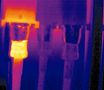
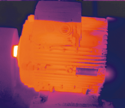
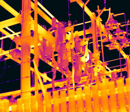
Fig: Application examples for thermal imaging technology (from left to right): loose fuse connection in an electrical system, overheating motor bearing, heat development in a transformer substation
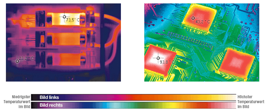
During the development of an electronic circuit and the associated circuit boards, a lot of time is invested in the design and arrangement of the components. A great deal of effort often goes into controlling the thermal loads, e.g. with thermocouples for temperature measurement, in order to ensure the safety and function of the circuit. In this context, heat development and heat dissipation via heat sinks play an important role. Possible questions that development engineers might ask themselves about the design include:
Measurements using a thermal imaging camera can easily answer such questions and avoid costly redesign measures. This allows the development team – or quality assurance – to ensure that a design also meets the thermal requirements as early as the prototype stage.
Defective electrical and mechanical components in a system usually become hot and can lead to costly breakdowns. Thermal imaging cameras are extremely effective diagnostic tools for many applications. In addition, industry's efforts to make production processes more and more efficient and to save energy resources are expanding the range of applications and measurement tasks for thermal imaging cameras (infrared cameras).
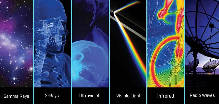
The wavelengths of thermal energy (infrared light) are much longer than those of the visible electromagnetic light spectrum. Thermal radiation is imperceptible to the human eye, comparable to radio waves (high-frequency waves). With thermal imaging technology, we can expand the spectrum visible to us by visualizing the thermal energy emitted by a target object.
Every object that has a temperature above absolute zero (-273 °C) emits electromagnetic heat radiation, including cold ice cubes, for example. And since visible light works independently of thermal radiation, thermal energy can be detected in both light and dark environments. The higher the temperature of an object, the more intense the infrared light emitted. Thermal imaging cameras produce images in which infrared radiation (heat radiation) is visible. They therefore enable non-contact and very precise temperature measurements.
A thermal imaging camera (IR camera) is a non-invasive measuring device that can detect thermal energy (infrared radiation) and convert it into electrical signals. These signals are shown on a display and used for temperature calculations. With the ability to precisely quantify heat in this way, performance monitoring can also be carried out.
The measurement is contact-free, i.e. without interfering with the running operation. It is therefore a non-destructive testing method that is suitable for almost all areas of industry, research or the electrical trade and can deliver fast results.
Useful areas of application for thermal imaging cameras are in hardware development, electronics, construction, quality assurance and production. Measurements with a thermal imaging camera can also provide information about potential sources of interference during service or maintenance.
Application examples for thermal imaging technology:
Fig.: Building thermography - visualizing weak points in the insulation
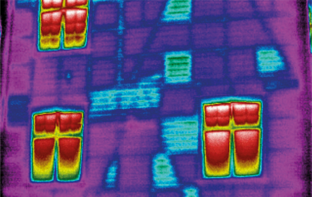
When starting with thermography, you should be aware that a surface that appears blue on the screen of the thermal imaging camera is not necessarily "cold". The decisive factor is the intensity of the heat radiation and the temperature difference between the respective surfaces (Figure in German).
The IR detector of the thermal imaging camera has a significant influence on the measurement result. The quality of a detector is assessed on the basis of its geometric and thermal resolution. The geometric resolution determines whether anomalies in the thermal image are sufficiently recognizable. The thermal resolution (Noise Equivalent Temperature Difference NETD), on the other hand, describes the smallest temperature difference that a thermal imaging camera can measure. This is particularly relevant for objects with very small temperature differences; the smaller the value of the thermal resolution, the more precise the measurement result.
To generate a thermogram, the IR detector of a thermal imaging camera captures several image dots (pixels). These are arranged in a sensor matrix. A matrix of 120 x 90 pixels comprises a total of 10,800 measurement points and therefore 10,800 individual measured values. A detector with 240 x 180 pixels generates four times as many measured values (= 43,200 pixels). This means that even small objects that are surrounded by a larger area can be easily recognized, e.g. a thermal bridge on a building façade.
Thermal imaging cameras in the entry-level price segment are available with a resolution from 80 x 60 pixels. For very small components, such as a hot wire in a switch cabinet, this may not be enough. Objects at a greater distance, e.g. in building thermography, also require a higher resolution.
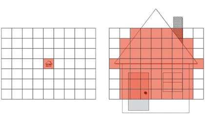
Fig.: Thermal image with 160 x 120 and 640 x 480 pixel resolution.
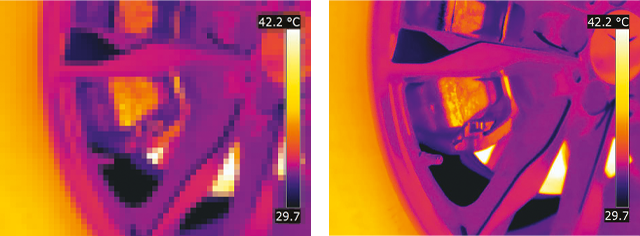
80 × 60 pixels = 4.800 measurement points
120 × 90 pixels = 10.800 measurement points
160 × 120 pixels = 19.200 measurement points
240 × 180 pixels = 43.200 measurement points
320 × 240 pixels = 76.800 measurement points
384 × 288 pixels = 110.592 measurement points
464 × 348 pixels = 161.472 measurement points
640 × 480 pixels = 307.200 measurement points
1.024 × 768 pixels = 786.432 measurement points
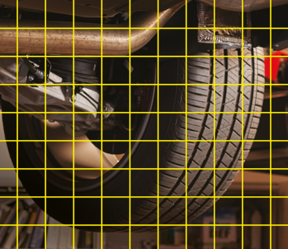
Normal resolution at a distance of 1 m.
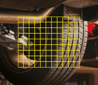
Normal resolution at half the distance.
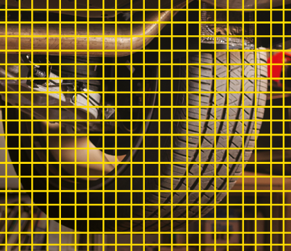
Higher resolution at 1 m distance.
The point size ratio indicates the distance at which precise temperature measurements are still possible for an object. The more pixels from the detector of the thermal imaging camera are directed at the target object, the more detailed the thermal image becomes. As the distance from the object increases, precise temperature measurements become more difficult. The higher the resolution of the thermal imaging camera, the further away the target object can be. Alternatively, the field of vision can be reduced. The digital zoom, on the other hand, cannot improve precision.
Fig: The greater the distance from the target object, the more difficult it is to take precise temperature measurements.
Image source: FLIR.com
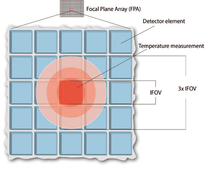
As many pixels as possible should always be aimed at the target object in order to obtain precise measured values. A few pixels may be sufficient to determine a temperature difference for a specific object area (qualitative). However, this is not sufficient for the precise determination of an average temperature for various reasons. For example, the thermal imaging camera could have faulty pixels or a sunlight reflection could provide a false positive and too high measured value.
Due to the optical dispersion, measures should be taken to ensure that the area in which the respective temperature value (point value) is to be measured is at least 3 x 3 pixels in size.
dataTec works with you to develop theoretical and practical knowledge of thermography and the corresponding interpretation of thermal images, as well as the subsequent documentation of your measurement results.
IR radiation (thermal radiation) is part of the electromagnetic spectrum. Its wavelength range is 780 to 1000 nm; it therefore borders on the wavelength range of the visible light spectrum (approx. 380 to 750 nm).
The emissivity describes how much infrared radiation an object emits compared to a hypothetical, idealized heat radiator (a black body that completely absorbs all electromagnetic radiation). The value is therefore between 0 (no absorption) and 1 (complete absorption). Objects with an emissivity of 0.8 to 0.95 are considered to have good thermographic properties.
The "instantaneous field of view" IFOV is calculated from the number of pixels and the aperture angle of the camera lens. It has the unit mrad (milliradian) and describes the smallest object that can still be depicted on the thermal image, depending on the measuring distance. On the thermal image, the size of this object corresponds to one pixel. The greater the number of pixels, the better the resolution of the camera and the smaller the IFOV. The ideal measuring spot of the IR camera can be determined from the IFOV. As a rule of thumb: ideal measuring spot ≈ 3 x IFOV.
The NETD is an indicator for the smallest possible temperature difference that a thermal imaging camera can measure (resolve). The lower the value of the thermal resolution (given in millikelvin, mK), the more precise the measured values are.
The reflectance is the ratio between reflected and incident infrared radiation or the ability of a material to reflect infrared radiation. This depends, among other things, on the surface quality of the material. A smooth or polished surface is usually more reflective than a rough or matt surface of the same material.
Thermography is an imaging measurement method for displaying the surface temperature of objects. The intensity of the infrared radiation emanating from a point serves as a measure of temperature. A thermal imaging camera converts invisible infrared radiation into electrical signals and visualizes them as a thermogram on a display.
The transmittance describes the permeability of an object or material to infrared radiation. When IR radiation strikes an object, it is partially reflected at the boundary surfaces, depending on the material properties (thickness, type, etc.), and partially or completely absorbed as it passes through. Most materials are not permeable to long-wave infrared radiation.
The market offers a practically infinite variety of thermal imaging cameras for users in the mechanical and electrical sectors. One of the basic considerations when choosing your camera is what type of system you want to check.
Maintenance professionals are interested in discovering problems as quickly as possible or enduring long inspection periods. Particularly ergonomic and user-friendly cameras that offer sufficient flexibility for a wide range of applications are suitable for this purpose.
In areas with motor control units that are difficult to access or on high-voltage systems, on the other hand, special lenses (wide-angle or telephoto lenses) can be useful for measurements from a greater distance. And if your tasks include measuring very high temperatures, e.g. on rotary kilns, your camera should be able to be calibrated accordingly. Which camera is right for you?
You are not quite sure yet or have further questions about the products? Do not hesitate to contact us. Whether directly on the phone or via online demo conveniently in front of your screen - our experts are there for you.
.webp "Seminar LabVIEW Core 1")
