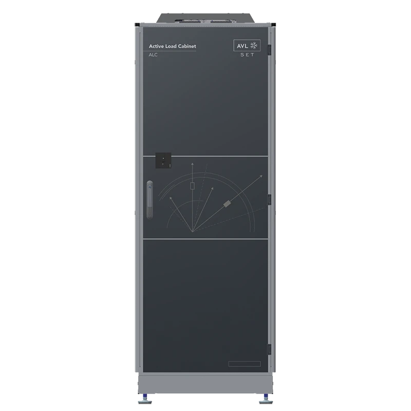
The AVL Active Load Cabinet (ALC) is an active electrical load designed for the functional testing and validation of high-voltage inverter hardware. It enables development teams to test inverters under defined and realistic electrical load conditions as early as the initial stages of development—even before the hardware, software, and the entire system are fully integrated. This allows potential hardware issues to be identified early on and reduces the effort required for troubleshooting and corrections in later development and integration phases.
A key advantage of the AVL Active Load Cabinet is the flexible adjustment of load conditions. In R-L mode, the system operates as an adjustable resistive-inductive load. Resistance and inductance can be parameterized during operation, allowing different electrical load conditions to be simulated without reconfiguring the test setup. Commissioning the device under test is designed for a simple test setup and, according to the manufacturer, requires only the definition of four parameters.
For more advanced tests, the system supports four-quadrant operation. This enables testing under active power conditions in both motor and generator modes. Additionally, the Active Load Cabinet can be used as a single-phase current source. Possible applications include, for example, the calibration of a test object’s internal sensors as well as connector testing. The system can also be integrated into existing laboratory and test bench environments via open communication interfaces.
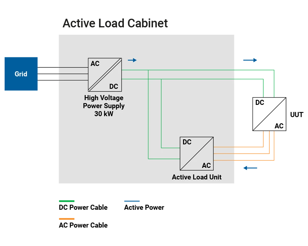
The AVL Active Load Cabinet is therefore particularly well-suited for research and development applications in the fields of power electronics and electromobility. It supports a wide range of functional tests on inverter hardware and enables the efficient use of existing test capacities. At the same time, the requirements for the electrical infrastructure remain relatively low: According to AVL, even at the UUT’s maximum power, a power connection of no more than 30 kW is required.
Product Features:
- Recommended minimum DC voltage of the unit under test (UUT): 300 VDC
- Maximum DC voltage of the unit under test (UUT): 1,000 VDC
- Rated phase current: 280 or 560 ARMS
- Maximum phase current (overload): 400 or 800 ARMS for 34 seconds (up to 900 V)
- Fundamental frequency: up to 1,000 Hz
- Interfaces: EtherCAT, Ethernet, and XCP over Ethernet
- Optional safety system: PROFINET
- Options for rotor position sensors: digital encoder, active magnetic sensor, and resolver sensor emulation
- Operating modes: R-L mode, four-quadrant operation, and single-phase current source
- Mains connection: maximum 30 kW, even at maximum UUT power